Light Sensing Plant Holder
Gadgetry, Fall 2018
For my gadgetry final project, I worked in a team of 3 to create a fully autonomous robotic plant maintenance system (aka RoboCrop). This device moves towards optimal lighting conditions and monitors soil moisture levels to maximize photosynthesis levels of a potted house plant.
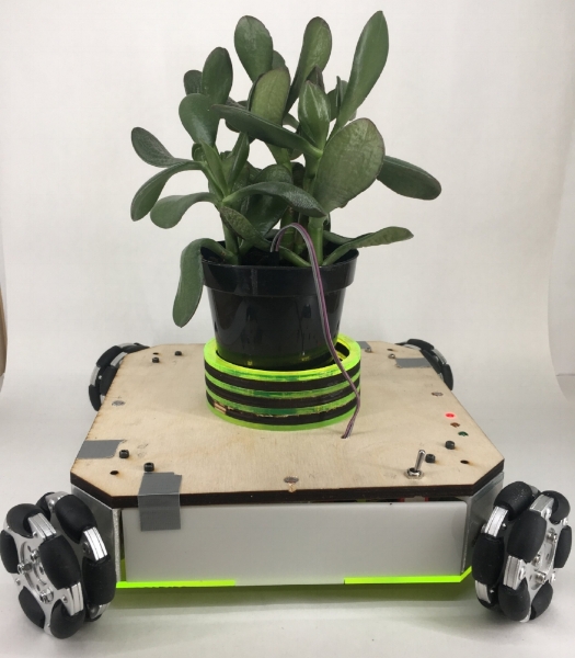
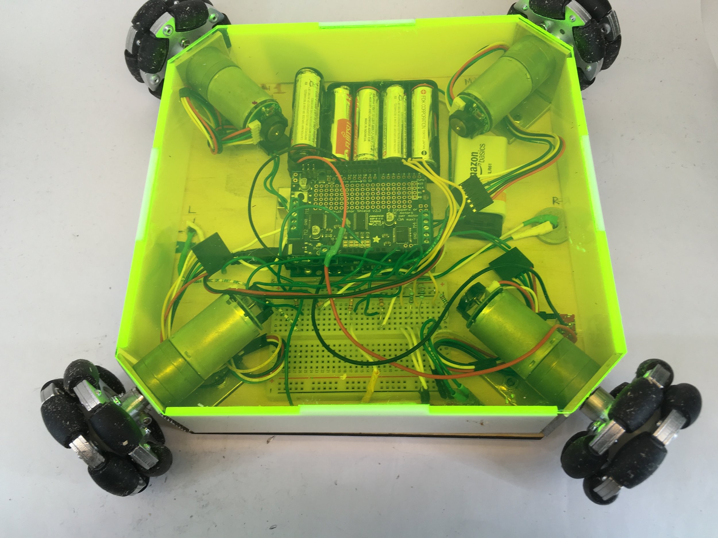
The design features 4 omni-wheels mounted to a wooden base with aluminum brackets and press fit shaft collars. 4 photoresistors are positioned around the body, secured by 3D printed housings. An Arduino Uno receives data from the photoresistors will move the plant in the direction of highest light intensity (1 of 8 possible directions). The Arduino is connected to a motor shield, which controls 4 DC motors. A moisture sensor in the soil detects when the plant should be watered and actuates an LED indicator (red = dry soil, orange = moderately dry soil, green = watered soil). A laser cut acrylic housing unit holds all electronic components securely on the underside of the body. The motor shield is powered by 6 AA batteries and is controlled with a switch. The Arduino and moisture indication system is powered by a separate 9V battery that remains on. For this project, I primarily worked on software and assisted with the design and physical assembly.
Testing
Testing of moisture system. Light turns from red to green as the plant is watered, indicating optimal moisture levels.
Manufactured Components

Manufactured shaft collar to attach omniwheels to DC motor shaft. Collar is press fit into the wheel and attaches to shaft via a set screw.

Machined aluminum brackets to secure DC motors.
Prototypes

Testing of first prototype. We found that in a bright room, the photo resistors we used responded better to shadows.
We went through several prototypes of this device, primarily focusing on adding functionality with each iteration. Our first prototype was a proof of concept of motor actuation using photoresistors. Rudimentary circular wheels were press fit onto a the shaft of a DC motor. 2 photo resistors on either side of the body controlled bidirectional movement of the robot. All components were fastened to a simple wooden body with custom machined aluminum brackets to attach toe motors. The motor shield were powered by an external power supply, which limited its range of motion.

Bottom of second prototype.
Our second prototype focused on creating a larger range of motion with omniwheels. Four photoresistors, positioned on each side of the body, actuated movement in four directions (diagonal functionality was included for the final prototype).This prototype still relied on a bench top power supply and lacked housing for electronic components, causing them to drag along the floor if not properly secured. See the video below for testing of the second prototype.