CodeBlox
Build18, Spring 2019

During a week-long buildathon, I worked in a 5 person team to create CodeBlox, modular blocks to teach children computational thinking skills. Blocks can be linked together to write code that controls a Bluetooth enabled robot. Traditional methods of learning to code are centered around a computer, which can limit accessibility. By creating tangible building blocks, we hope to better engage kinesthetic and visual learners, as well as introduce programming concepts to kids at a younger age. Additionally, a physical implementation of coding encourages collaboration between peers.
For our demonstration, we used CodeBlox to create a simple line following robot program, seen below. Our project won the Intel Award for most outstanding project, Rockwell Automation Award for best proof of concept, and Overall Sponsor Award for most outstanding project.
Design
My role in this project focused primarily on the physical design and assembly of each tile. The tiles are constructed from laser cut wood. Each tile has a 2 sets of 5 pogo pins and copper strips to send and receive data from neighboring tiles. This allows the user to build code both horizontally and vertically. Magnets in the corners of each tile allow them to snap together and make the connections between the pogo pins and copper strips. To facilitate debugging, when each tile is activated, a green LED will blink. If there are any syntactical errors or bugs that cause the code to not compile, the code will run up to that point, and the problematic tile will have a red LED light up. A master tile receives data from each block and sends it via Bluetooth to the robot.

Model of initial concept.
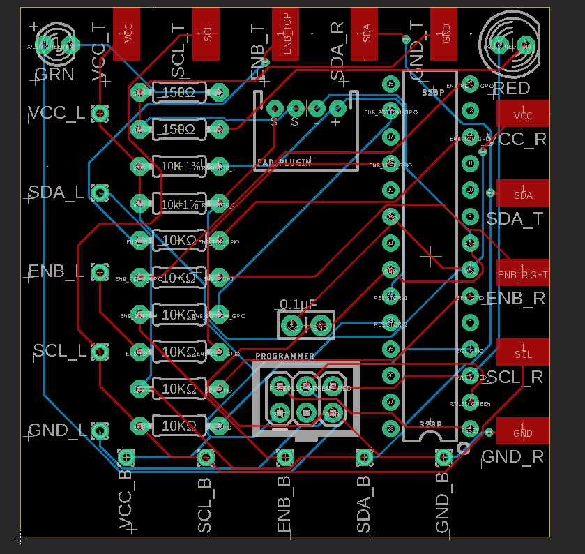

Each tile has a custom PCB board with an ATMEGA328p chip for processing. The pogo pins, copper strips, and connections to the top panel are soldered to the board.
Each block is generic, and does not take a value until a laminated pad is placed on top. This reduces the number of tiles that need to be fabricated. Pads are connected to the top of the tile with magnets wrapped in copper tape that connect to the PCB chip inside. The underside of the pad contains resistors attached to washers. Each pad is assigned a unique resistance value that encodes the operator.
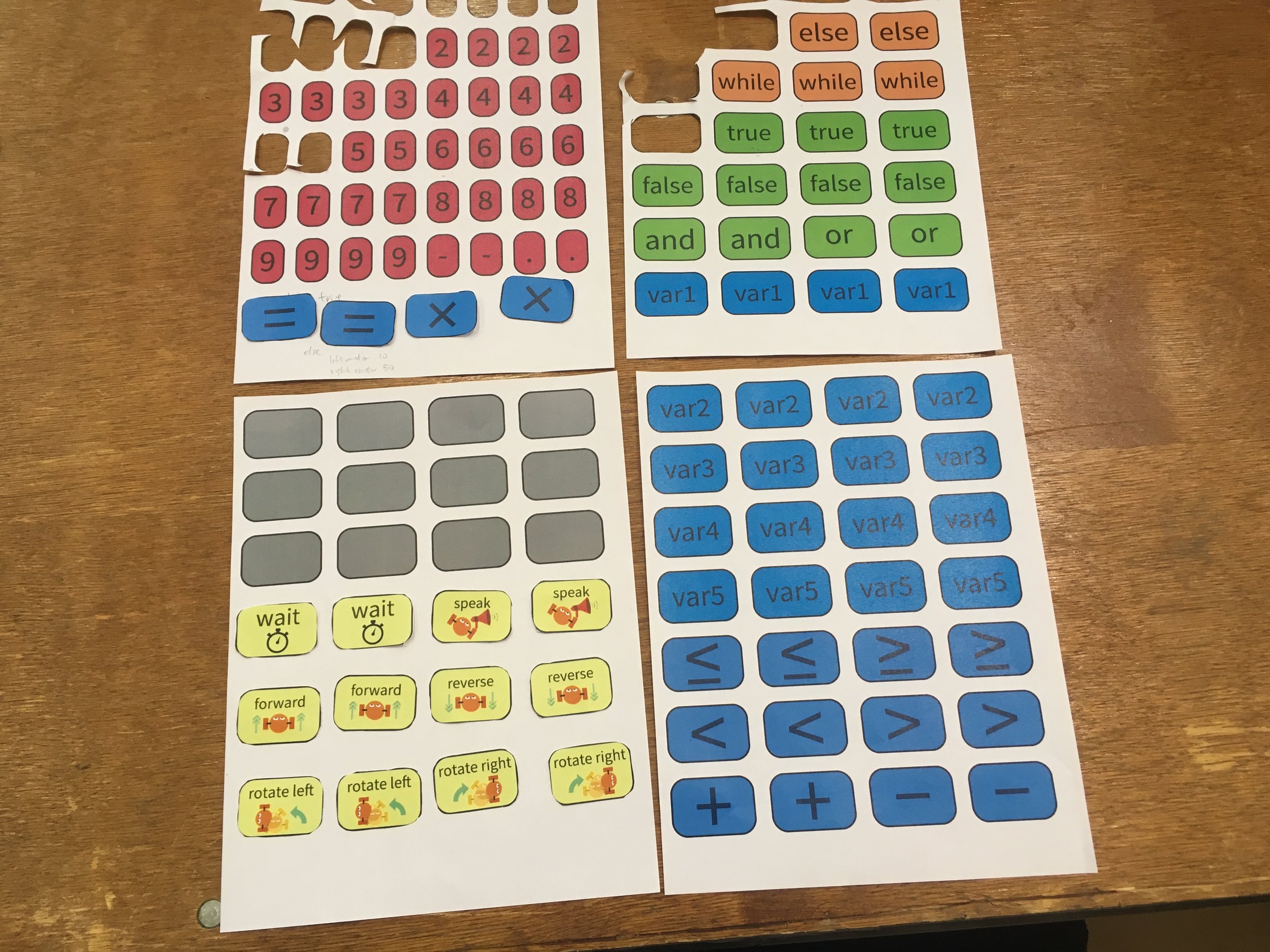
Pads to place on top of the tiles.

Back of assembled pads. Each operator has a unique resistance value.
Assembly

All of the tile exteriors laser cut and assembled. We made 28 tiles in total.

Attaching magnets to the corners of each tile with epoxy. The magnets are centered vertically to provide a force in line with the pogo pins.

Close up of magnets. Polarity allows correctly oriented tiles to snap together in all 4 orientations.

Threading copper tape through the slots on the top and right panels of each block.

Close up of the receiving end.

Spring loaded pins are soldered to the board and then threaded through each hole.

Copper strips and top panel connections soldered to the board.