Mechanical Crane
Stress Analysis, Spring 2018

Crane mounted onto playing field.
The objective of this project was to build a mechanical crane powered by a servo motor. The crane was to be mounted to a playing field, where it had to pass through an obstacle to lift a weight at least 2 inches in the vertical direction. The crane had to lift the weight twice without deflection. In addition, no part of the mechanism was allowed to touch the playing field or obstacle.
Our design featured a rectangular base with an overhang where the arm was attached. We utilized a truss structure for the base in order to reduce deflection when lifting the weight. The crane arm was a 28 inch long triangular truss, modeled after a tower crane. The servo motor was housed near the end of the arm, where it was attached to a delrin strip that served as the lever arm. Our team successfully completed the task of lifting the weight 2 inches while remaining under the 20 ounce weight limit.

Side view of the final design.
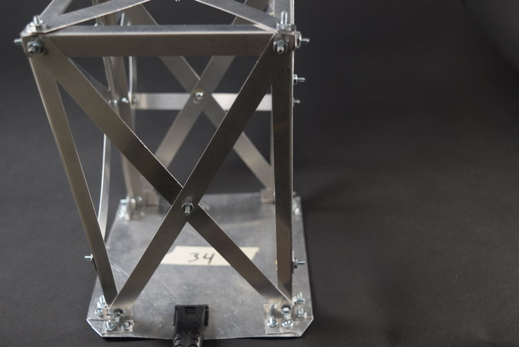
Front view of the base. The front and back of the base were supported by X-shaped trusses.
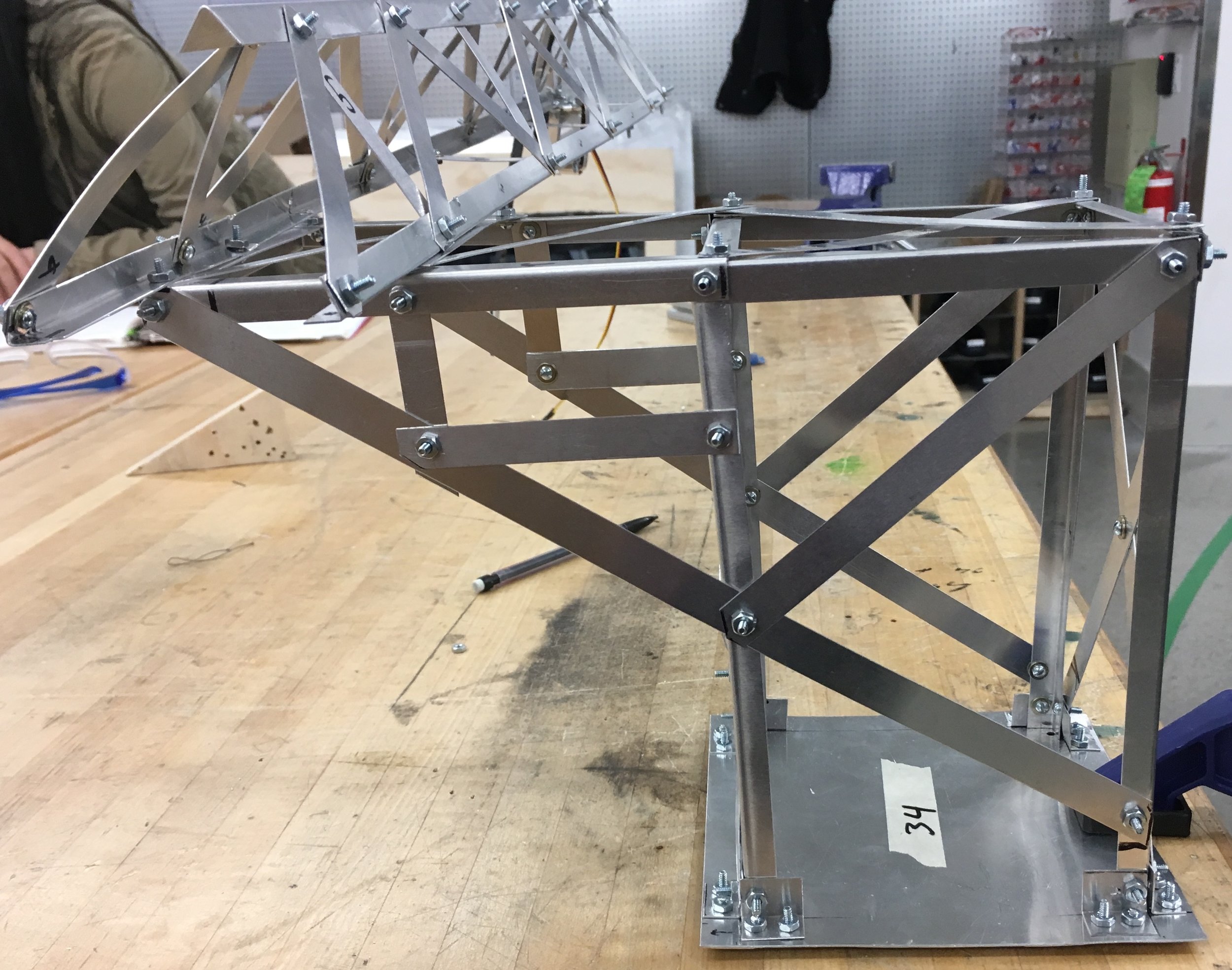
Side view of the base. The overhang extends approximately 6 inches, supported by a V shaped truss.
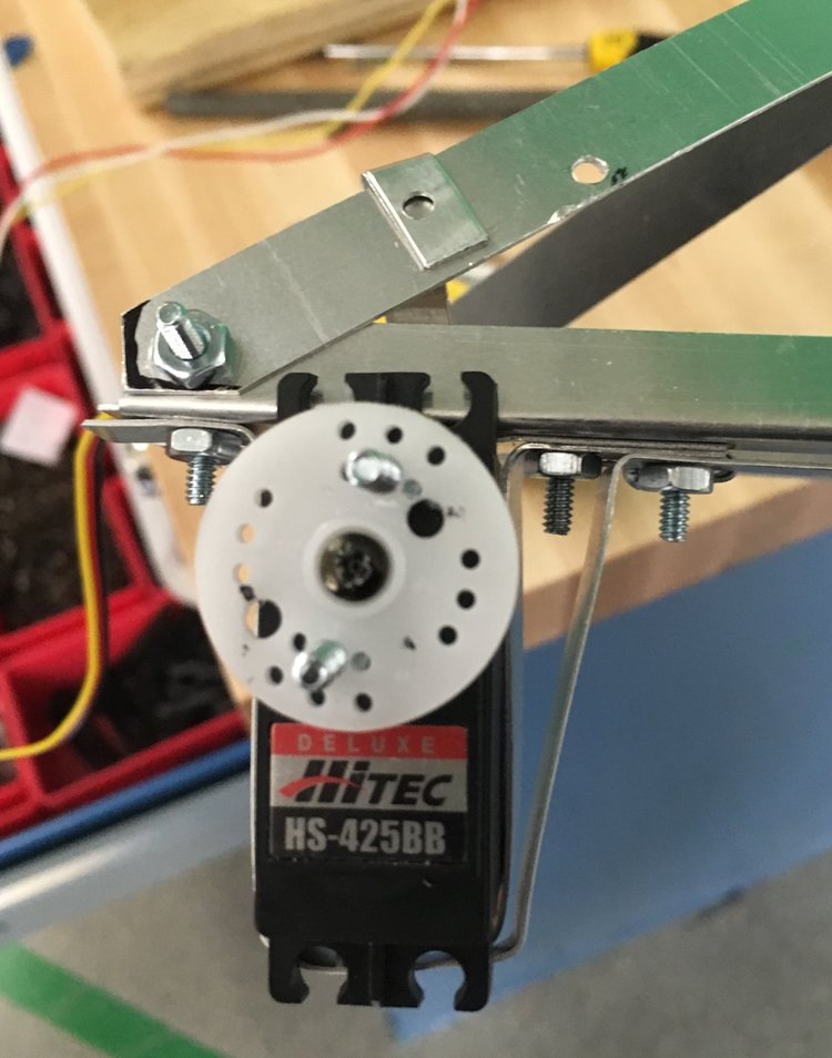
The servo motor was held in place with several strips of aluminum screwed into the bottom of the crane arm.

Delrin strip with an aluminum hook used to lift the weight.
Testing Rig
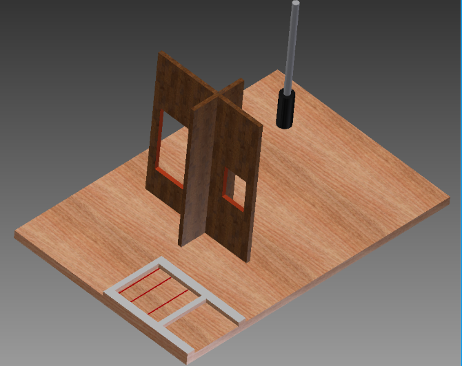
3D View of the testing rig. The base of the crane clamped onto the bracket in the lower right hand corner. It then passed through one of the two holes of the obstacle and lifted the weight on the rod in the upper left corner. The crane was not allowed to touch any part of the playing field except for the clamp and the weight.