Staircat
Engineering Design II, Fall 2019
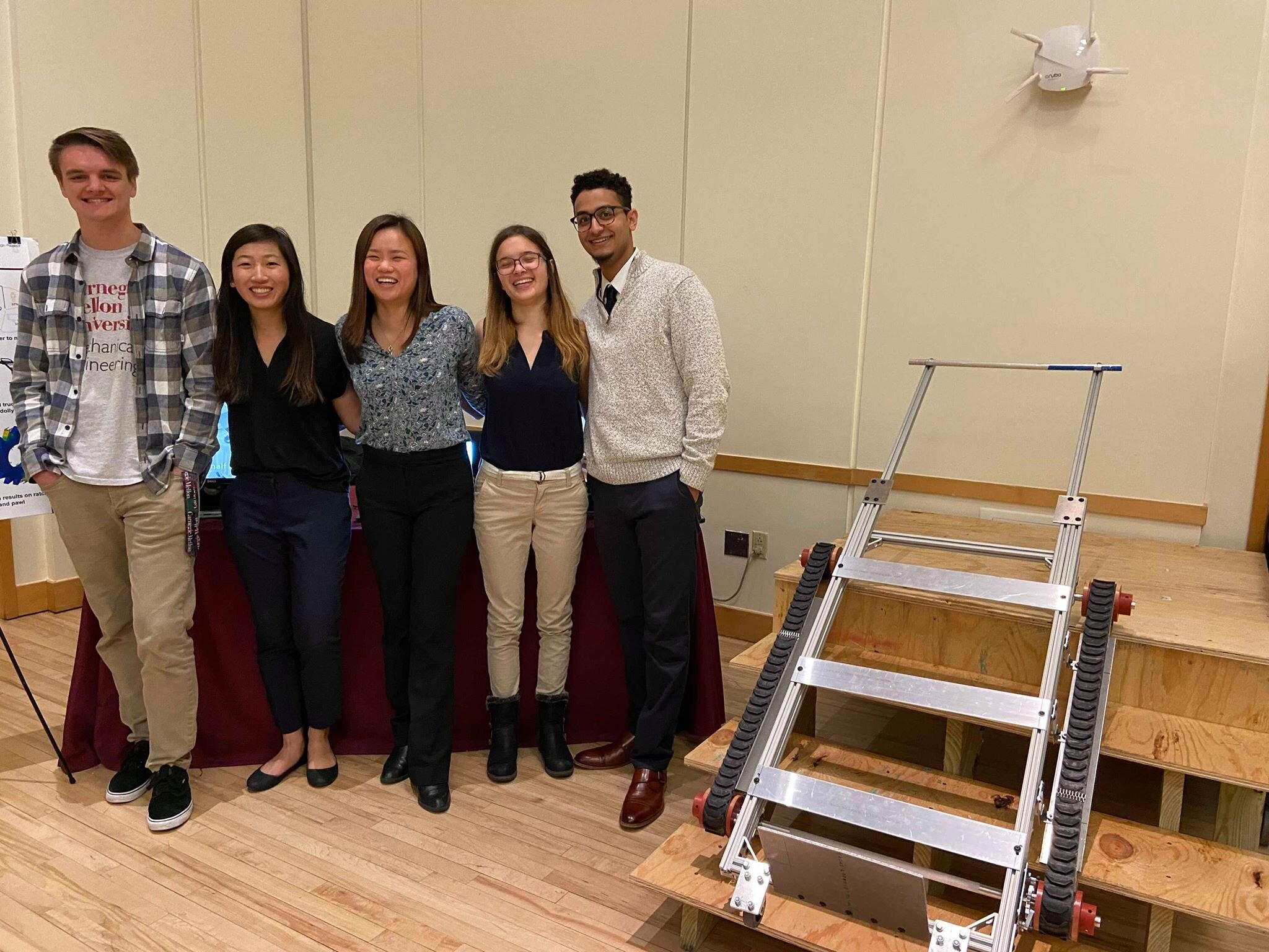
For my senior capstone design project, I worked in a team of 5 to build StairCat, a safe and ergonomic moving assistant. StairCat looks to solve the problem of moving heavy and/or bulky objects up stairs, which can be difficult and dangerous. Many possible solutions exist to this problem, but products such as hand trucks provide minimal benefit, while more robust solutions that incorporate motorized lifting systems cost several thousand dollars and are far too expensive for the average consumer. Our target demographic is DIY movers and moving equipment rental companies.
StairCat differs from a conventional hand truck in its ratcheted tread system, which allows users to seamlessly transition from moving on flat ground to traversing up stairs. The unidirectional motion of the ratchet provides a safety mechanism, allowing the user to stop at any point on the steps. Over the course of the semester, we performed market research, built and demoed several prototypes, and conducted user studies to improve the ergonomics of our product.
Design
On flat ground, the StairCat performs similarly to a conventional hand truck. To use this device, the user first slides the front plate underneath the box or object to be moved. Then, the user tips the device back, balancing it on the two wheels to move the boxes around on flat ground. When approaching a flight of stairs, the safety hook, shown below in yellow, is removed. This allows the tread frame to rotate backwards and engage with the steps. Then, the handle is extended to the appropriate length and locked, allowing the user to maintain an upright posture while pulling. Once on the stairs, a ratcheted pulley system keeps the treads from slipping down the stairs, and the user can stop the device at any point on the steps.

Final prototype, constructed with T-slotted aluminum framing
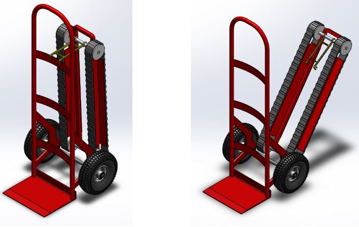
CAD rendering of final mass manufactured design, shown when in use on flat ground (left) and with the treads engaged for use on stairs (right).
Ratchet
The ratchet gear and pawl subsystem, shown below, is the key safety component preventing the StairCat from falling backwards on stairs. This system is composed of a pawl that engages with a gear with uniform but asymmetrical teeth. Each tooth has a moderate slope on one side and a much steeper slope on the other. When the gear is moving in the forward direction, the pawl easily slides over the gently sloped edge of the tooth. A torsional spring forces the pawl into the space between the teeth. However, when the gear moves in the backwards direction, the pawl will catch against the steep edge of the tooth, locking it in place and preventing any further motion. Both the ratchet and pawl were CNCed from aluminum.

CAD model of ratchet system

Ratchet gears, machined from stock aluminum.
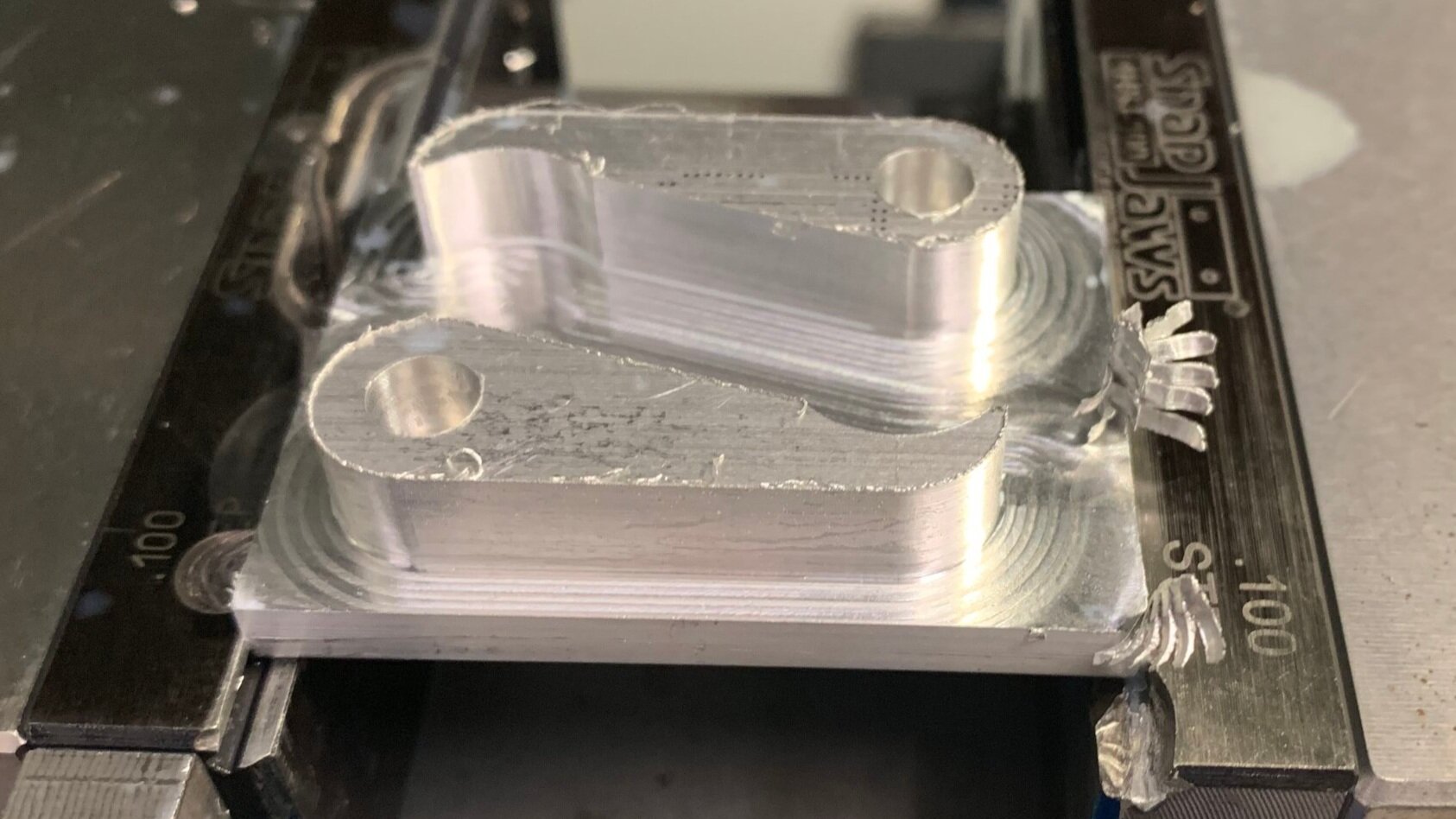
Pawls after CNC operation.
Treads
The treads were selected for their high friction against multiple surfaces. We tested our device on concrete, hardwood, and carpeted stairs. The corresponding tread pulleys were lathed from plastic cylinders. The pulleys, shown below, have an inset for the treads with a high friction tape to prevent lateral slipping of the treads. A set screw keeps the pulleys rigidly attached to the axle. A rail was added to the underside of the treads to maintain tension when on the steps.

Tread pulley with set screw and friction tape
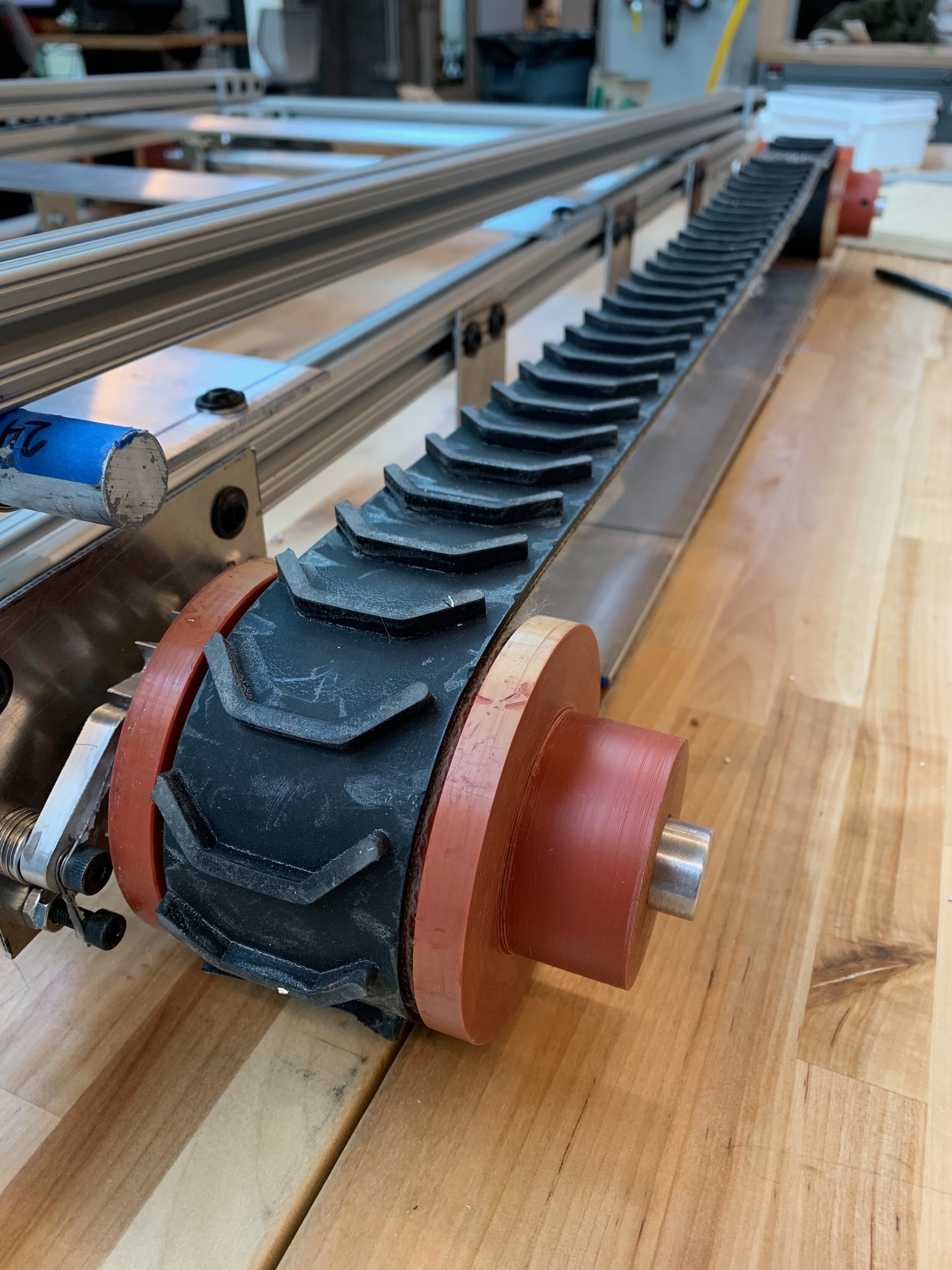
Tread installed on the device. The back wheel contain the ratchet and pawl system to prevent backwards motion.
Design Iterations
Prototype 1
This prototype focused on making a proof of concept for the ratcheted tread system, the key safety feature of this product. The ratchet and pawl were CNCed from aluminum. Our prototype was able to reliably stop on steps and hold a weight of 50 pounds, failing at the connection between the spring and the pawl. We used a basic wooden frame that was pushed up the stairs to explore design difficulties of the frame, axles, and handle. Later design iterations focus on user testing and improved ergonomics.

Testing of first prototype
Prototype 2
This prototype focused on scaling up the previous frame for a more robust performance on stairs and improving the ergonomics of the frame and handle. Our design consists of an aluminum T-slotted frame and handle to allow for quick modifications based on user feedback. Initially, the frame began as an adjustable pushing design, similar to Prototype 1. However, after testing with this design, we found that pushing was not ergonomic. Due to the higher mass of this frame, the user must get much lower to the ground in order to successfully push the device up the stairs. We moved to a pulling frame design, allowing for the user to maintain a more upright position while going up the stairs, reducing the risk of injury. The added wheels roll easily on flat ground and in tight spaces, which allows for improved maneuverability on landings.

Initial push-cart based design

Design after switching to pulling

Testing for prototype 2. On this prototype, the box lays on the tread frame and the handle hinges upwards.

Testing of final prototype. The handle is lower on the frame to counteract the moment from loading and is adjustable to allow for users to stand upright. Additionally, the hinge was moved from the handle to the tread frame.